Games0.5
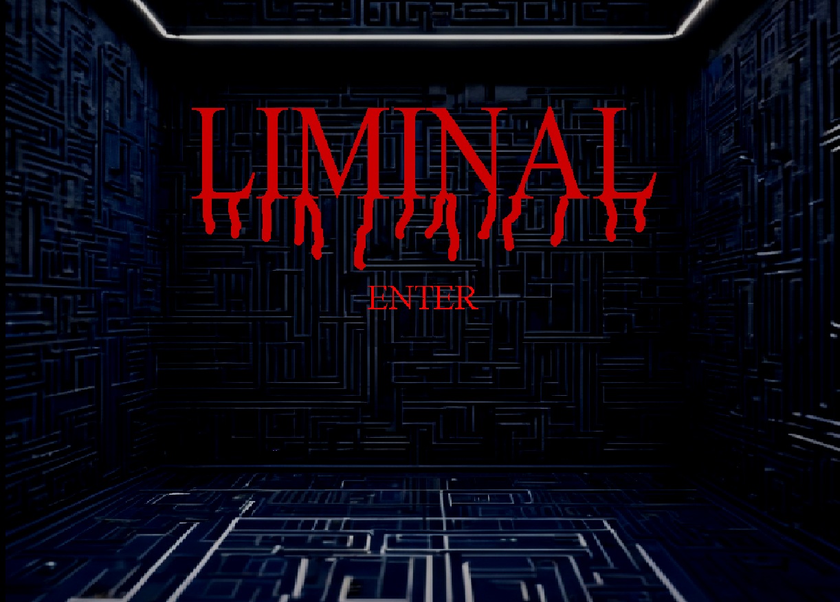
Liminal
An atmospheric game that opens in a dark, maze-patterned room. Free to play online in your browser.
High-voltage electronics, resonant circuits and iterative design
My MYP Personal Project: investigating and improving a spark-gap Tesla coil through research, prototypes, testing, and revision.
Presentation
01 / The question
For my MYP Personal Project I set out to optimize a spark-gap Tesla coil — a resonant, high-voltage device associated with Nikola Tesla. My product goal was a working, improved setup, judged against criteria for function, accessibility and finish, estimated efficiency, safety considerations, and budget.
My learning goals were to understand high-voltage and resonant circuits better, to develop research and information-literacy skills by comparing approaches and judging advice, and to practise creative problem-solving by taking a design from theory into experiment. The project sits in the MYP global context of Scientific and Technical Innovation.
It was an investigation into the device and its design — not an attempt to prove that Tesla coils are a practical way to transmit power wirelessly.
02 / Research
I compared driver and oscillator circuits, and researched spark-gap design, capacitor arrangements, wiring, insulation, and cooling and safety considerations, using several online sources.
I also discussed the design with two of my school physics teachers, Mr Kassis and Mr Lykkas. Rather than treating every suggestion as equally reliable, I weighed advice against what I could test and the components I actually had.
Ideas I put into practice included a multiple-mini-capacitor (MMC) arrangement, a bleed resistor, and shorter primary wiring. I used circuit simulation to explore a self-oscillating driver before building it.
03 / Iteration
My first approach, a modified Colpitts oscillator, did not suit the characteristics of the salvaged high-voltage transformer I was using.
An astable multivibrator driver proved inefficient and led to transistors overheating and failing. A MOSFET-based attempt then did not switch as intended with the drive available.
I simulated a self-oscillating driver concept and then tested it in practice, revising components — including an IRF540 MOSFET and an added current-limiting resistor.
When the coil later stopped working, I suspected a short in the secondary coil, but traced the fault to a damaged MOSFET. A DIY high-voltage component also proved ineffective, so I looked for parts with more suitable voltage ratings.
Arcing between the primary and secondary coils led me to change their spacing and coupling and to add improvised insulating material. Adding a ferrite core raised the measured secondary inductance from 6.28 mH to 13.5 mH.
04 / Outcome
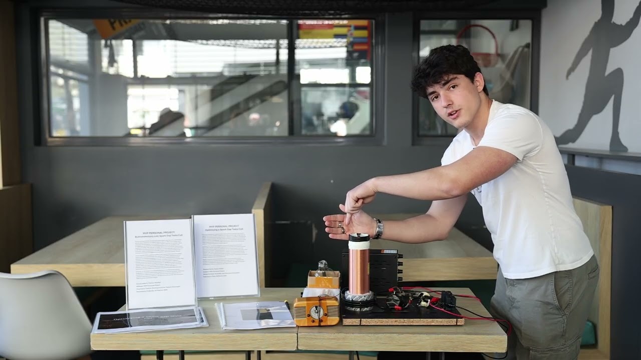
The final build is a physical, tested prototype assembled on an open, accessible base, with the coil, driver circuit, capacitor arrangement, and an adjustable spark gap I built.
According to my observations it produced visible arcs of roughly 3 cm and stronger electromagnetic effects than my first prototype. Better tuning may have contributed to that improvement as much as the ferrite core did. Its appearance stayed prototype-like, but it was easy to observe and maintain.
05 / Evaluation
These are my own assessments and estimates from the project report, not independently verified measurements. Voltage figures were inferred from arc length. High-voltage equipment is dangerous — this page is a record of a supervised school project, not a guide to building one.
06 / Reflection
07 / Looking ahead
This school project gave me a hands-on way to explore circuits, resonance, high voltage, component choice, testing, and iterative design — the topics that make me want to study electrical engineering. It was a learning experience rather than professional engineering work, and it showed me how much there still is to learn.
An atmospheric game that opens in a dark, maze-patterned room. Free to play online in your browser.
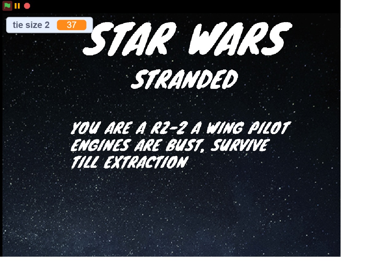
A space survival game — you are an RZ-2 A-wing pilot with busted engines, surviving until extraction.
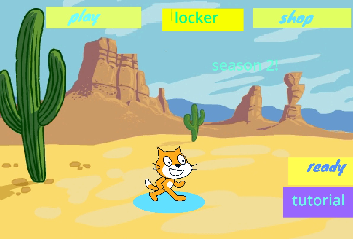
A desert-themed cat battle game with a lobby, locker, and shop — now in its second season.